


The Galileo Energetic Particles Detector
Galileo EPD Handbook
Chapter 1. Instrument Summary
Original, Pre-Challenger Time-of-Flight Subsystem
Source: Jim Cessna, SDO/PAO-0040, January 20-21, 1981
The TOF engineering model was brought to APL for integration in October 1980. It was found to have some susceptibility to spikes on the power supply line, due to a design problem in the baseline maintenance circuit. This was corrected by installing the circuit shown in the lower part of Figure 1-29. The Gain of A is several thousand up through about 300 MHz. Because these are not stable baseline DC amplifiers, they require a maintenance feedback circuit, labeled B in the diagram. This has been modified to help the amplifiers reject noise as well. The simplified system transfer function near the lower edge of the diagram shows that above 40 kHz the gain is equal to the straight-through gain of the amplifier chain. The negative feedback lowers the gain to unity below 28 Hz, and takes it to the reciprocal of the gain of B at lower frequencies. This lowers the effect of power supply noise at the 2/3 second rate.
Figure 1-29. Baseline restorer and L.F. noise rejection
threshold and zero crossing chains

Table 17 shows the results of power supply noise tests on the circuit in Figure 1-29.
TABLE 17. CMS TOF Power Supply Noise Tests
Power Supply Ripple for Worst Case Threshold
| Freq. | +6 | -6 | +3 | -3 |
| 10 Hz | ±0.5 v | ±135 mv | ±0.5 v | ±0.5 v |
| 30 Hz | 0.5 | 150 mv | 125 | 350 mv |
| 100 Hz | 0.5 | 100 mv | 50 | 300 mv |
| 300 Hz | 0.45 | 80 mv | 10 | 125 mv |
| 1 kHz | 90 mv | 55 mv | 5 | 60 mv |
| 3 kHz | 13 mv | 35 mv | 3 | 17 mv |
| 10 kHz | 6 mv | 13 mv | 2 | 5 mv |
| 30 kHz | 16 mv | 13 mv | 5 | 23 mv |
| 100 kHz | 100 mv | 200 mv | 70 | 200 mv |
| 300 kHz | 250 mv | 0.45 v | 0.45 v | 0.5 v |
| 1 MHz | 0.5 v | 1.0 v | 0.3 v | 1.0 v |
| 3 MHz | 1.0 v | 2.0 v | 0.75 v | 0.33 v |
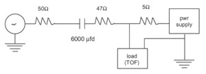
A signal generator was capacitively coupled to each of the power supply inputs as a constant current source with the circuit shown at the top of the figure. The 5 ohm resistor is used to simulate a power supply with a source impedance of 5 ohms. The power supply for the experiment will have a source impedance of less than 2 ohms. Table 17 shows the peak to peak noise on the junction of the 5 ohm and 45 ohm resistors that would produce a discernible signal at the output of the amplifiers between 10 Hz and 3 MHz.
The table still shows a fair amount of susceptibility to noise at 10 kHz, which is close to the frequency of the power supply spikes. To decrease the noise rejection further, passive filters were put into the power supply lines with 1 kHz breakpoints. These will produce about 20 dB of rejection at 50 kHz. J1, J2, and J3 in Table 18 represent the three identical channels in the Time of Flight electronics.
TABLE 18. Galileo TOF
Worst Case Timing Variation Over Temp. and Over 10 ns - 100 ns
| -40º C | -25º C | -10º C | +12º C | +25º C | +45º C | +60º C | |
| J1 | +1.9 ns | +1.5 ns | +0.8 ns | 0 | -0.4 ns | -0.8 ns | -1.1 ns |
| J2 | +1.5 | +1.1 | +0.7 | 0 | -0.3 | -0.5 | -0.5 |
| J3 | +1.6 | +1.2 | +0.6 | 0 | -0.3 | -0.9 | -0.8 |
Table 18 shows the temperature stability of the TOF electrons with +12 degrees C used as a reference point. The figures in the table are the variations in a set of Time of Flight measurements with a range from 0 to 100 ns. These are worst case measurements which cluster close to 100 ns total TOF. The valid event pulse (J·K·7(Tm)) is discussed in Table 19.
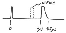
TABLE 19. CMS TOF J·K·(T)m Pulse (actually J·(T)m only)
| J "event" pulse = pur window approximately 4.5 ms | |
| Tm pulse | |
| Threshold: 115 ns | |
| Width: approximately 4.5 ms | |
| Example: | |
| J · (T)m Pulse (for T>Tm): | |
Return to the CMS Subsystem Index
Return to Galileo EPD Handbook Table of Contents Page.
Return to main
Galileo Table of Contents Page.
Return to Fundamental
Technologies Home Page.
Updated 8/23/19, Cameron Crane
QUICK FACTS
Mission Duration: Galileo was planned to have a mission duration of around 8 years, but was kept in operation for 13 years, 11 months, and 3 days, until it was destroyed in a controlled impact with Jupiter on September 21, 2003.
Destination: Galileo's destination was Jupiter and its moons, which it orbitted for 7 years, 9 months, and 13 days.