


The Galileo Energetic Particles Detector
Galileo EPD Handbook
Chapter 1. Instrument Summary
Introduction
The Energetic Particles Detector (EPD) system was developed by the Johns Hopkins University Applied Physics Laboratory (APL) in collaboration with the Max Planck Institute for Aeronomy (MPAe) as part of the NASA Galileo Program. The Galileo spacecraft was launched from the space shuttle in 1989 and achieved an orbit around Jupiter in 1995. There, the EPD measured the detailed energy and angular distribution of ions (Z>=1) from 0.020 MeV to 55 MeV, electrons from 0.015 MeV to >=11 MeV, ion composition from 0.010 MeV/nuc to >=10 MeV/nuc, and from helium nuclei to nuclei heavier than iron. These data have allowed a definitive determination to be made of the properties of the Jovian magnetosphere.
The EPD consisted of two principal measuring instruments: a Low Energy Magnetosphere Measurement System (LEMMS) and a Composition Measurement System (CMS). The LEMMS consisted of a magnetic analyzer and solid state detector telescopes to separate and analyze electrons and ions in the energy ranges described above. The CMS consisted of combinations of thin and thick solid state detectors employing discriminators, DE vs. E techniques, and time of flight (TOF) measurements to identify and measure ion composition and intensities.
In addition, the EPD had a stepping platform with a motor drive and control system for rotating the detectors to obtain complete spherical coverage of electron and ion particle distribution in the Jovian magnetosphere, a data and command system, an inflight calibration system, a power system for utilizing spacecraft supplied power, and thermal control system.
MPAe provided the LEMMS and CMS telescopes and LEMMS analog electronics. The National Oceanic and Atmospheric Administration (NOAA) Space Environment Laboratory (SEL) provided the original CMS TOF electronics. The TOF circuitry in the upgraded TOF detector actually flown was the joint responsibility of MPAe and JHU/APL. APL provided the overall EPD including all internal and external interfaces and spacecraft integration. Calibration and tests were carried out jointly by JHU/APL, MPAe, and Bell Laboratories.
Galileo EPD Characteristics:
| Mass: | 10.5 kg | ||||||||||||
| Power: | 6W electronics; 4W heaters | ||||||||||||
| Bit Rate: | 912 bps | ||||||||||||
| Size: | 19.5 cm x 27 cm x 36.1 cm | ||||||||||||
| Two bi-directional telescopes mounted on stepper platform | |||||||||||||
| 4π steradian coverage with 52 to 420 samples every 7 s/c spins (~140 s) | |||||||||||||
| Geometric Factors: | 6 x 10⁻³ - 5 x 10⁻¹ cm2 ster, dependent on detector head | ||||||||||||
| Time Resolution: | 0.33-2.67 s, dependent on rate channel | ||||||||||||
| Magnetic Deflection: | ΔE x E, and time-flight systems | ||||||||||||
| Energy Coverage: | (MeV nucl-1) | ||||||||||||
|
|||||||||||||
| 64 rate channels plus pulse height analysis | |||||||||||||
The purpose of this website is to provide a concise collection of essential facts about the EPD instrument for the purpose of data analysis and interpretation.
Overview and System Summary
Source: R. W. McEntire, SDO/PAO-0040, Jan. 20-21, 1981
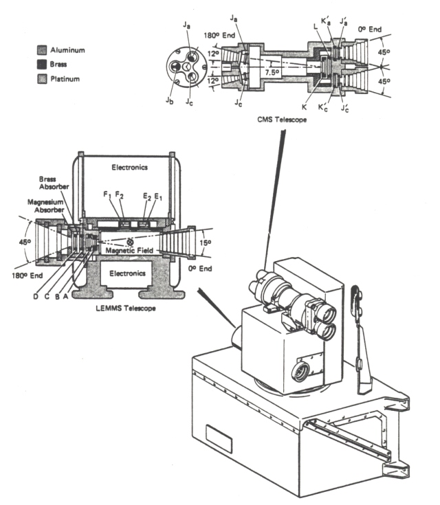
Figure 1-1 provides an overview of the pre-Challenger EPD system organization. A block diagram is given in Figure 1-2. Figure 1-3 provides mechanical overviews, both pre-Challenger and post-Challenger.
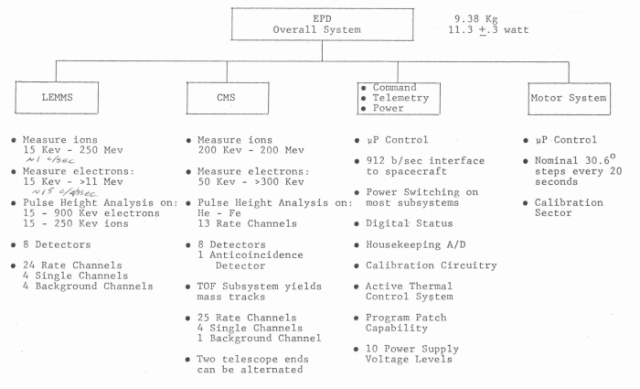 |
Figure 1-1.
Overview of pre-Challenger EPD system organization. Source: Steve Jaskulek; EPD Team Meeting, 28 February, 1984. |
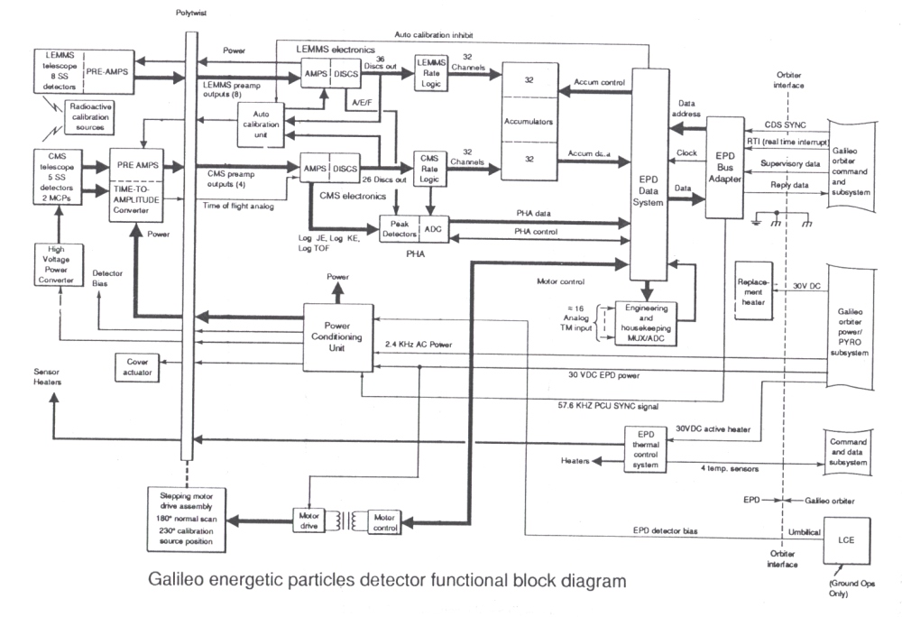 |
Figure 1-2. Galileo EPD functional block diagram. Original source: R. W. McEntire; SDO/PAO-0040, Jan. 20-21, 1981; this updated version from draft of paper published in Space Science Reviews, 60, 385, 1992. |
Figure 1-3. EPD configuration. Left: pre-Challenger (source: R. W. McEntire; SDO/PAO-0040, Jan. 20-21, 1981); right: post-Challenger (source: Critical Design Review, Dec. 21-22, 1987).
 |
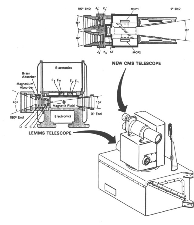 |
Figure 1-3 shows the bidirectional LEMMS and CMS telescopes, mounted on the rotating platform of the EPD. The LEMMS is the main low energy ion and electron detector head in the EPD. Detectors A and B detect low energy ions as they come through a honeycomb collimator on the 0 degree end of the telescope.
The rotating platform steps through 7 sectors, 30.6 degrees apart. This sweeps the telescopes over a bit more than 180 degrees, which, combined with the spacecraft spin, gives full unit sphere coverage.
Electrons below 1 MeV coming through the 0 degree aperture are deflected into the E1 and F1 electron detectors, which are backed up by the E2 and F2 anti-coincidence detectors to reduce background. Ions and very high energy electrons and ions are detected by the stack of A, B, C and D detectors.
There is a 3.2 mm thick brass absorber between C and D, a 2 mm aluminum absorber (labeled magnesium in Figure 1-3) in front of the D detector and a platinum absorber about 3 mm thick between detectors B and C. The aluminum absorber is 0.5 g/cm2, the brass is 2.6 g/cm2, and the platinum is 6.5 g/cm2.
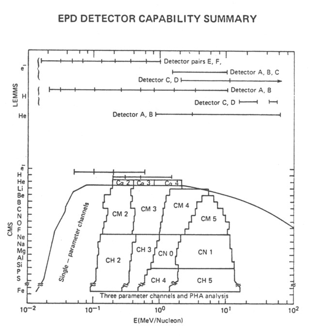
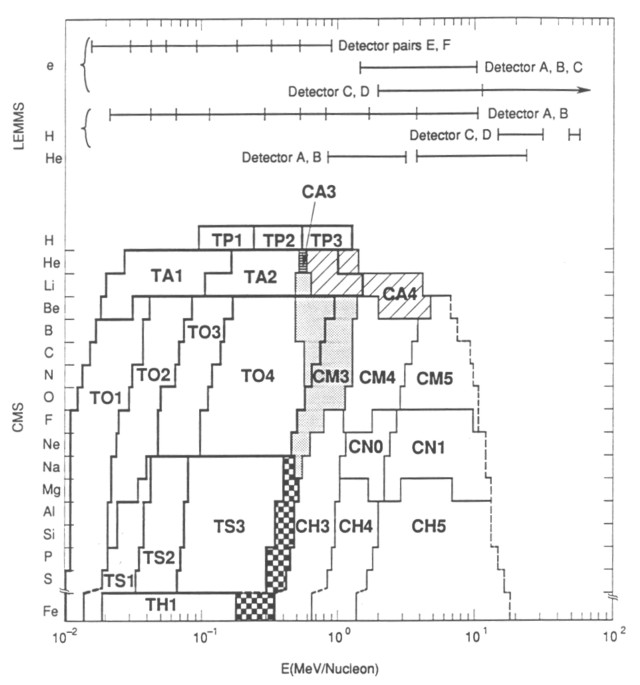
There are 24 ion and electron rate channels on LEMMS. There are also 4 singles channels on A, B, C and D, and 4 background channels on the electron detectors. The rate channels provide coverage for electrons above 15 keV, and coverage for ions above 20 keV, with the low energy ions covered by the A and B detector pair and the ABC and CD detector combinations covering the higher energy electrons and ions. A schematic of the energy coverage for the LEMMS and the CMS is shown in Figure 1-4.
Figure 1-4. EPD detector capability summary. Left: pre-Challenger (source: R. W. McEntire; SDO/PAO-0040, Jan. 20-21, 1981); right: post-Challenger (source: draft of paper published in Space Science Reviews, 60, 385, 1992).
 |
 |
The last column in Table 1 gives the readout rate of the individual EPD channels--the longest readout interval is 4/3 sec. The readout scheme was changed from sector based to time based because of uncertainties about having a fixed and known S/C spin rate. In our present time based system, when the S/C spin rate changes, the angular sector covered in one readout interval will change. At a nominal spacecraft spin rate of three rpm, a readout every 4/3 second corresponds to a 24 degree sector. The EPD rotating platform steps 30.6 degrees every 20 seconds (a nominal time base slightly greater than the spacecraft spin period) to provide a full unit sphere scan in about 140 seconds.
TABLE 1. ENERGETIC PARTICLES DETECTOR CHARACTERISTICS
| Detectors |
Energy
Range (MeV/Nucl) |
Species |
Energy Intervals |
Geometric Factor (cm2sr) |
Readout Interval (1/3 sec) |
| LEMMS | |||||
| A,B,C | 0.020-3.4 | Z>1 | 8 | 0.01 | 1.2 |
| 3.4-10.5 | Z=1 | 1 | 0.005 | 4 | |
| 0.85-3.1(He) | Z>2 | 1 | 0.005 | 4 | |
| 3.1-62.5 | Z=1 | 1 | 0.005 | 4 | |
| 1.5-10.5 | Electrons | 1 | 0.005 | 4 | |
| E1,E2 | .015-.100 | Electrons | 4 | 0.005 | 1,2 |
| F1,F2 | .100-1.0 | Electrons | 4 | 0.005 | 2 |
| C,D | >2 | Electrons | 1 | 0.5 | 4 |
| >11 | Electrons | 1 | 0.5 | 4 | |
| 15.5-28 | Z=1 | 1 | 0.5 | 4 | |
| 45-55 | Z>1 | 1 | 0.5 | 4 | |
| CMS | |||||
| J(a,b);Ja | 0.20-.050 | Z>1 | 2 | 0.11 (0.23) | 4 |
| (Total E) | 0.17-0.39 (He) | Z>2 | 1 | 0.11 (0.23) | 4 |
| 0.16-0.45 (O) | Z>3 | 1 | 0.11 (0.23) | 4 | |
| 0.07-0.10 (S) | Z>15 | 1 | 0.11 (0.23) | 4 | |
| J(a,b)KL(d) | .50-1.4 | Z=1 | 1 | 0.009 (0.23) | 4 |
| Ja' Ka' | .38-1.8 | Z=2 | 2 | 0.009 (0.23) | 4 |
|
(dE/dx vs E (vs TOF for unprimed detectors)) |
.41-10.7 (O) | Z=3-9 | 3 | 0.009 (0.23) | 4 |
| .91-11.7 (Na) | Z=10-4 | 2 | 0.009 (0.23) | 4 | |
| .33-.80 (S) | Z>10 | 1 | 0.009 (0.23) | 4 | |
| .80-.13 (S) | Z>15 | 2 | 0.009 (0.23) | ||
| Jc; Jc' | .08-.19 (He) | Z>2 | 1 | 0.005 (0.12) | 4 |
| (Total E) | .08-.15 (O) | Z>3 | 1 | 0.005 (0.12) | 4 |
| 0.025-0.025 | Z>15 | 1 | 0.005 (0.12) | 4 | |
| JcKL | .19-.45 | Z=2 | 1 | 0.009 (0.11) | 4 |
| Jc' Kc' | .14-.59 | Z=3-9 | 1 | 0.009 (0.11) | 4 |
|
(dE/dx vs.
E (vs TOF for unprimed detectors)) |
.11-.37 (S) | Z>10 | 1 | 0.009 (0.11) | 4 |
| JK; J'K' | .05-.30 | Electrons | 3 | 0.01 (0.34) | 4 |
Notes:
(a) In addition, PHA gives 4.5 high
resolution events/sec for CMS and 47 channel energy spectra
for LEMMS ions (20-250 keV) and electrons (20-200; 100-800
keV).
(b) Geometry factor is for: unprimed detectors (primed
detectors).
(c) At nominal 3 RPM: 4/3 sec - 15 readouts/spin (or 24
"sectors"), etc.
(d) Species and energy coverage different in some channels
for primed detectors, or if TOF is off.
(e) Nominal values are given here. Definitive values in Table
6 govern.
Next: Mechanical System Overview
Return to Galileo EPD Handbook Table of Contents Page.
Return to main
Galileo Table of Contents Page.
Return to Fundamental
Technologies Home Page.
Updated 8/23/19, Cameron Crane
QUICK FACTS
Mission Duration: Galileo was planned to have a mission duration of around 8 years, but was kept in operation for 13 years, 11 months, and 3 days, until it was destroyed in a controlled impact with Jupiter on September 21, 2003.
Destination: Galileo's destination was Jupiter and its moons, which it orbitted for 7 years, 9 months, and 13 days.