The Galileo Energetic Particles Detector
From Space Science Reviews
LEMMS
The Low Energy Magnetospheric Measurements System
The LEMMS telescopes are designed to measure low to
medium energy ion and electron fluxes with wide dynamic
range and high angular (<20 deg) and temporal (1/3 to 4/3 s)
resolution. As stated previously, a full 4pi coverage of the
unit sphere is obtained by the use of a stepping platform in
conjunction with satellite spin.
The LEMMS detector head is a double-ended telescope
containing eight heavily shielded silicon solid state
surface barrier totally depleted detectors providing
measurements of electrons from 15 keV to > 11 MeV, and ios
from 22 keV to eV to ~55 MeV, in 32 rate channels.
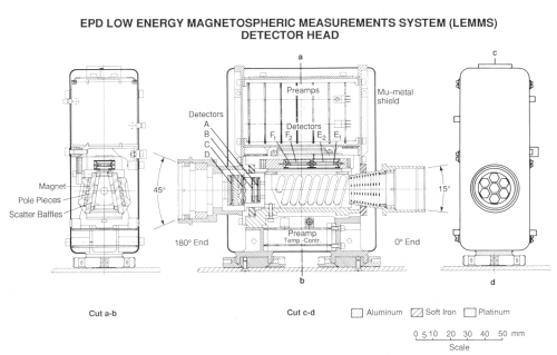 |
Detail of the EPD LEMMS detector head. |
LEMMS Channel Descriptions
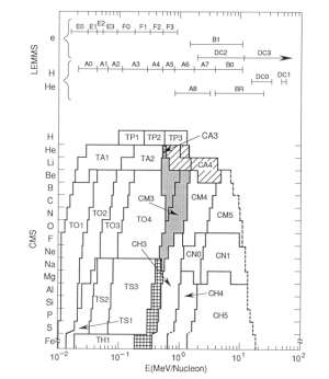
Channel         Species         Energy Range    Geometric Factor
Name                            (MeV)           (cm**2 sr)
--------------------------------------------------------------------------------
A0              Z >= 1          0.022-  0.042   0.006
A1              Z >= 1          0.042-  0.065   0.006
A2              Z >= 1          0.065-  0.120   0.006
A3              Z >= 1          0.120-  0.280   0.006
A4              Z >= 1          0.280-  0.515   0.006
A5              Z >= 1          0.515-  0.825   0.006
A6              Z >= 1          0.825-  1.68    0.006
A7              Z >= 1          1.68 -  3.20    0.006
A8              Z >= 2          3.50 - 12.4     0.006
B0		Z  = 1		3.20 - 10.1     0.006
B1		electrons      ~1.5  - 10.5	0.006
B2		Z  = 2	       16.0  -100.	0.006
DC0		Z >= 1	       14.5  - 33.5     0.5
DC1		Z >= 1	       51.   - 59. 	0.5
DC2		electrons	     >~ 2.	0.5
DC3		electrons	     >~11.	0.5
E0              electrons       0.015-  0.029   0.006*
E1              electrons       0.029-  0.042   0.020*
E2              electrons       0.042-  0.055   0.030*
E3              electrons       0.055-  0.093   0.033*
F0              electrons       0.093-  0.188   0.028*
F1              electrons       0.174-  0.304   0.007*
F2              electrons       0.304-  0.527   0.016*
F3              electrons       0.527-  0.884   0.018*
AS		singles		all counts	0.006
				in detector
BS		singles		all counts	0.006
				in detector
CS		singles		all counts	0.5
				in detector
DS		singles		all counts	0.5
				in detector
EB1		background	sidewise penetrators
EB2		background	E1E2 coincidences
FB1		background	Sidewise penetrators
FB2		background	F1F2 coincidences

*  Geometric factor determined from table in paper by Y. Wu, T.P.
   Armstrong.
The geometric factor of the collimator and magnetic optics system has been analyzed by extensive computer modeling (Wu and Armstrong, 1988). The energy dependent aperature-integrated geometry factors for detectors E1 and F1 are shown here.
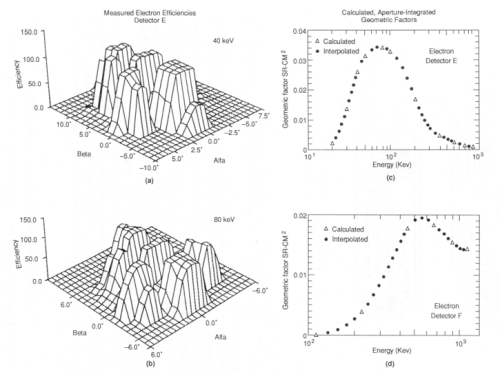 |
Response of the EPD LEMMS low energy electron detectors. The geometric factor, as calculated from a detailed simulation shown as a function of energy. |
A diagram of the LEMMS analog electronics is included
next. The unbuffered preamp tail-pulse output signals are
sent down the polytwist wiring harness to three LEMMS analog
boards, where the signals are amplified and shaped. All
signal processing in the LEMMS channels is done in the
linear domain. Comparator-like discriminator circuits
assigned to each of the eight channels fire whe pre-defined
threshold levels are exceeded.
The resulting discriminator outputs are sent to the rate
logic electronics, where combinatorial logic is used to
define 32 rate channels (event bins).
LEMMS data also are processed through a pulse height
analyzer (PHA) that produces 13 46-channel energy spectra
per major frame.
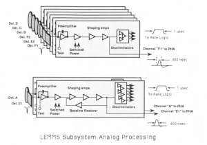 |
Block diagram of LEMMS analog electronics. |
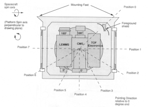
The detector heads are mounted on a platform and rotated by a stepper motor contained in the main electronics box. The stepper motor positions as seen looking down onto the top of the EPD along the motor rotation axis can be seen in the figure below
The combination of the satellite spin and the stepper
motor rotation (nominally stepping to the next position
after each spacecraft spin) provides 4pi steradian coverage
of the unit sphere. The zero degree ends of the two
telescopes have a clear field of view over the unit sphere
and also can be positioned behind a foreground shield/source
holder for background measurements and in-flight
calibrations. The 180 degree ends experience obscuration
effects in motor positions 4, 5 and 6 caused by the
magnetometer boom and foreground shield.
The primary elements of the system are the LEMMS/CMS
detector heads with their analog electronics, the motorized
scanning system, the digital support electronics, and the
data system. The following figure shows a functional block
diagram of the EPD.
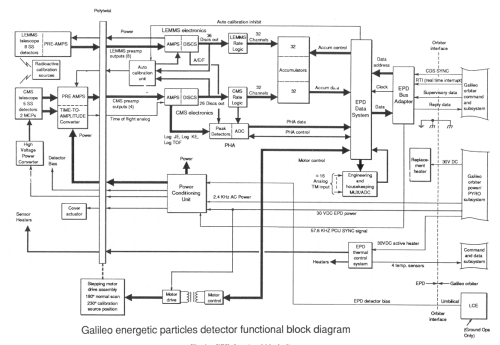 |
EPD functional block diagram. |
Return to main
Galileo Table of Contents Page.
Return to Fundamental
Technologies Home Page.
Updated 8/23/19, Cameron Crane
QUICK FACTS
Mission Duration: Galileo was planned to have a mission duration of around 8 years, but was kept in operation for 13 years, 11 months, and 3 days, until it was destroyed in a controlled impact with Jupiter on September 21, 2003.
Destination: Galileo's destination was Jupiter and its moons, which it orbitted for 7 years, 9 months, and 13 days.


