


The Galileo Energetic Particles Detector
Galileo EPD Handbook
Appendices
Appendix C. Magnetometer Subsystem (continued)
Mag Telemetry
Source: GLL-3-280, Rev. B, Appendix A; March 15, 1985
These paragraphs describe the format and content of the output of the Magnetometer Subsystem.
MAG Packet. The schematic of a MAG Packet is shown in Figure 3. One packet is placed in each LRS frame.
Figure 3. MAG Packet
| Title | Instrument Status |
1st Science Sample |
2nd Science Sample |
3rd Science Sample |
| Data Offset | 0 | 16 | 64 | 112 |
| Bits/Packet | 16 | 48 | 48 | 48 |
Instrument Synchronicity. The contents of the MAG Packet can be uniquely determined from the data within the packet and the SCLK Mod 91 count. The MAG Synchronization Index is equal to the SCLK Mod 91 count.
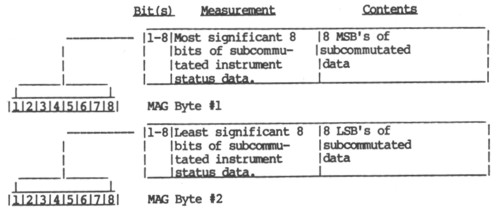
Instrument Status. The contents of the Instrument Status section are two bytes of subcommutated analog and digital status values. This is shown in Table 1. The positions are shown relative to synchronization index in Table 2.
Table 1. Instrument Status (MSB is bit 1)
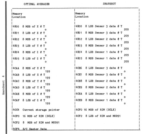
Data Buffer Format. The data provided in the OPTIMAL AVERAGING and SNAPSHOT modes of the magnetometer is stored in a data buffer provided between locations 4800-4D00. This data includes the current storage pointer, start time, sector data and 200 vector samples of the magnetic field in the OPTIMAL AVERAGER MODE. In the SNAPSHOT mode, the data is stored in reverse order due to timing restrictions in the interrupt handling routines, and includes the start time and 210 vector samples. Format details are provided in Table 3 This data is read out in 16 16-bit blocks once each MOD91 frame from address 4800-4D00 and placed in the magnetometer subcommutated data from SI=74 through SI=89 (see Table 2). In order to collect one complete buffer of data, approximately 40 frames must be read. The data readout continuously cycles between addresses 4800-4D00.
Table 3. MAG Data Buffer Content
In the "Optimal Average" mode timing between vectors is controlled by the AVERAGE # found in SI47 of the instrument status data. The timing is always a multiple of the MOD91 timing and is defined by
DELTA T = (AVERAGE # +1) * 60.6666
In the "Snap Shot" mode timing between vectors is 33.3 ms or 30 vectors per second.
1st Science Sample. The 1st science sample section contains 3 (16 bit) samples of sensor data collected exactly 1 MOD 91 count prior to the SCLK MOD 91 count of the LRS frame they are within. The 3 (16 bit) samples are 3 measurements corresponding to the X, Y, and Z axes, respectively. The measurements are output in field units, which can be converted to nano-teslas (nT) by dividing by the scale value provided in the instrument statue (SI=0, Table 2).
FieldnT = (FieldFU) / SCALE (*)
(*) SCALE shall be commandable to a selected value.
Each sample is a 16 bit two's complement word which ranges from -32768 to +32767.
2nd Science Sample. The 2nd science sample section contains 3 (16 bit) samples of sensor data collected at 222.22 ms after the MOD 91 count prior to the SCLK MOD 91 count of the LRS frame they are within. The 3 (16 bit) samples are 3 measurements corresponding to the X, Y, and Z axis, respectively. The measurements are output in field units, which can be converted to nano-Teslas (nT) by dividing by the scale value provided in the instrument status (SI=0, Table 2).
FieldnT = (FieldFU) / SCALE
Each sample is a 16 bit two's complement word which ranges from -32768 to +32767.
3rd Science Sample. The 3rd Science Sample section contains 3 (16 bit) samples of sensor data collected at 444.44 ms after the MOD 91 count prior to the SCLK MOD 91 count of the LRS frame they are within. The 3 (16 bit) samples are 3 measurements corresponding to the X, Y, and Z axis, respectively. The measurements are output in field units, which can be converted to nano-teslas (nT) by dividing by the scale value provided in the instrument status (SI=0, Table 2).
FieldnT = (FieldFU) / SCALE
Each sample is a 16 bit two's complement word which ranges from -32768 to +32767.
Telemetry Mode Changes. Upon the application of system power, MAG shall automatically configure itself to a standby mode. MAG data packets will contain no valid data in this mode. Commanded telemetry mode changes are processed every RIM.
Next: Mag Housekeeping
Return to Galileo EPD Handbook Table of Contents Page.
Return to main
Galileo Table of Contents Page.
Return to Fundamental
Technologies Home Page.
Updated 8/23/19, Cameron Crane
QUICK FACTS
Mission Duration: Galileo was planned to have a mission duration of around 8 years, but was kept in operation for 13 years, 11 months, and 3 days, until it was destroyed in a controlled impact with Jupiter on September 21, 2003.
Destination: Galileo's destination was Jupiter and its moons, which it orbitted for 7 years, 9 months, and 13 days.