


The Galileo Energetic Particles Detector
Galileo EPD Handbook
Chapter 1. Instrument Summary
CMS Rate Channels - Pre-Challenger Information
Source: Steve Gary, SDO/PAO-0040, January 20-21, 1981
The signal processing that occurs between the detectors and the data system is shown in Figure 1-26. This presentation discusses the CMS Analog Filter, the CMS Analog Electronics and the CMS Rate Logic.
Figure 1-26. Galileo EPD signal processing.
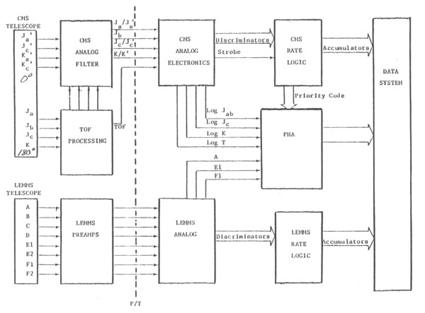
The preamps for the primed end of the CMS telescope are on the CMS Analog Filter board. The preamps for the 0 degree end of the telescope are in the TOF system but drive the CMS Analog Filter as well.
Figure 1-27 shows a detailed block diagram of the CMS TOF Assembly, the CMS Analog Filter, and the CMS Analog Electronics. The CMS Analog Filter and CMS TOF Assembly are on the rotating platform and the CMS Analog Electronics are in the base of the experiment.
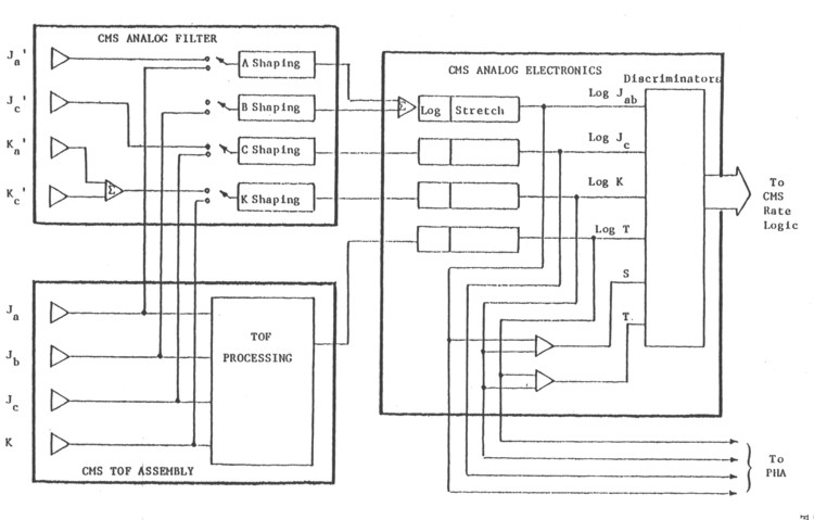 |
Figure 1-27.CMS TOF assembly, analog filter and analog electronics, pre-Challenger. |
A full analysis of the expected CMS rate channel passbands resulting from the analog and logical electronic processing of the DE and TOF signals is given in Section 2.2.4. Table 14 gives the CMS logical channel definitions. Table 15 gives the discriminator thresholds for CMS.
The CMS was not designed to pulse height analyze protons. A proton channel is present only as a backup for LEMMS. There is no pulse height analysis in the CMS below the JaO level. The strobing on the proton channel is independent of the strobing above JaO level. The instrument can be counting protons very rapidly in the single parameter CP1 and CP2 channels and the dead time for the high Z particles will be unaffected. The time of flight end of the CMS has a large geometry factor for just the J detectors, and a much smaller geometry factor for the J detector in coincidence with the K detectors. (This is why every effort has been made to keep protons striking the J detectors from being able to saturate the system.)
Since the main strobe (JaO) comes from the front detectors, if it were set at the JaPl level, for example, then there would be a very large geometry factor for being saturated by protons and a much lower geometry factor for getting a J and K coincidence for high Z particles. An additional consideration is that the shorter time constants in the Time of Flight circuitry require that the energy threshold for full 3 parameter analysis be higher than would be required for ΔE x E analysis alone. Thus, unlike Voyager, we have not intended to take any CMS PHA data on protons.
The 0 degree end of the CMS telescope (with one 50 square mm 5 micron Ja' detector and one 25 square mm 2 micron Jc' detector) has no Time of Flight capability. The 180 degree end of the CMS telescope has a 7.5 cm TOF spacing between the J and K detectors. Because of this, the two ends of the telescope have different geometry factors for JK coincidence. The 5 micron detector in the 0 degree end has a twenty-five times larger geometry factor than the sum of both 5 micron detectors in the 180 degree end and the two micron detector in the 0 degree end has a geometry factor more than 120 times larger than the similar detector on the 180 degree end (for JK coincidence).
The 0 degree end has a geometry factor close to the geometry factor of the similar LECP ΔE x E telescope on Voyager, while the 180 degree TOF end has a geometry factor close to the much smaller one obtained when the Voyager 2 telescope was in the near encounter stow mode.
The two ends of the CMS will do very well in the middle Jovian magnetosphere. The Time of Flight system will operate to well within 10 RJ. The 0 degree end will operate to within 30 RJ and should saturate somewhere between 20 RJ and 30 RJ. For most of the mission in the outer magnetosphere, the 0 degree end will be used.
The 0 degree end will be stowed when necessary to protect the large geometry factor detectors when the spacecraft nears perijove.
The 0 degree end and 180 degree end of the CMS time-share all of their electronics except for the Time of Flight, so only one end can be operated at a time. Table 14 shows the definition of the nominal CMS channels.
There is no Time of Flight capability on the prime end (0 degree end) of the telescope. The Time of Flight capability on the 180 degree end of the telescope can be commanded OFF if desirable.
Table 16 contains a list of most of the commands used in the CMS system. The JA, JB, JC and L commands are present to keep a failed part of the system from locking up the rest of the electronics.
Figure 1-28 contains a block diagram of the pulse height analyzer. An analog to digital converter is used to digitize the outputs of the peak detectors. After the signals from the telescope pass through the multiplexers, they are processed in the same way, no matter which end (0 degree or 180 degree) of the telescope they came from.
Figure 1-28. EPD Pulse Height Analyzer block diagram.
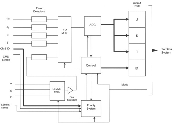
Data is held in the output ports so that it can be sampled by the data system. In the CMS mode, the J, K, and T channels are read out whether or not there is a Time of Flight measurement. The CMS ID (eight bits) identifies which rate channel and which J detector correspond to each event and the priority ordering under which the event was analyzed.
Next: Original, Pre-Challenger Time-of-Flight Subsystem
Return to the CMS Subsystem Index
Return to Galileo EPD Handbook Table of Contents Page.
Return to main
Galileo Table of Contents Page.
Return to Fundamental
Technologies Home Page.
Updated 8/23/19, Cameron Crane
QUICK FACTS
Mission Duration: Galileo was planned to have a mission duration of around 8 years, but was kept in operation for 13 years, 11 months, and 3 days, until it was destroyed in a controlled impact with Jupiter on September 21, 2003.
Destination: Galileo's destination was Jupiter and its moons, which it orbitted for 7 years, 9 months, and 13 days.