


Investigation of the Magnetosphere of Ganymede with Galileo's Energetic Particle Detector
Ph.D. dissertation by Shawn M. Stone, University of Kansas,
1999.
Copyright 1999 by Shawn M. Stone. Used with permission.
3.6 State Vectors and EPD Look Directions
The SPICE kernel system allows the calculation of the state of any body with respect to any other body in the solar system. All that is needed is the body code number and the ephemeris time desired. For example, the body code for Galileo is -77 and the body code for Ganymede is 503. The SPICE routines return a six dimensional state vector S={x,v} in J2000 coordinates (illustrated in Appendix A). S can then be transformed into any body centered frame desired such as GSII:
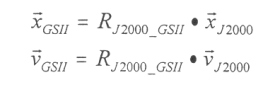 |
[3.9] |
by the transformations that we have defined in section 3.5.2.
One of the most important calculations in this work is the determination of the EPD look directions in GSII coordinates. Without this, the results would be meaningless. Fortunately, with the SPICE kernel system and the right ascension and declination angles and the motor position and spin sector supplied with the EPD binary rate files, this calculation is straightforward. The transformation matrix RSCC_GSII has already been defined in Equation 3.5. From the motor step position (0-7) and the spin sector (1-16) provided by the EPD rate file, the EPD look direction LSCC in SC can be calculated. Then using RSCC_GSII, the look direction in GSII can be calculated by the transformation LGSII=RSCC_GSII·LSCC.
3.6.1 Calculating SC from Motor Step Position and Spin Sector
Spacecraft coordinates were defined in section 3.4.3. The process of calculating the EPD look direction in SC begins with the motor step position (0-7) and the spin sector (1-16). Table 3.5 and Table 3.6 give the angles associated with these numbers. Figure 3.14 shows the orientation of the EPD look direction (collimator axis) as a function of θ and Φ. The look direction in spacecraft coordinates is then derived by the transformation of a unit vector aligned with the Z axis in SC by rotation of the step and spin phase angles:
|
|
[3.10] |
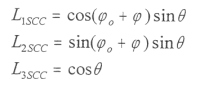
where Φo is the EPD offset from the spin axis, Φo=π/16 for 16 sectors. Figure 3.15 shows an example of the overall geometry of the G2 encounter in GSII coordinates including the orientation of the EPD look direction along the trajectory.
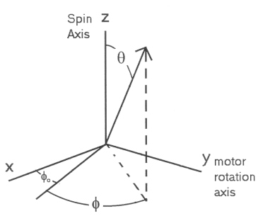 |
Figure 3.14. Illustration of the EPD look direction in SC. The angle θ is the motor position angle shown in Table 3.5. The angle Φ is the spin phase of the Galileo spacecraft and Φ0 is the offset of the detector from the spin axis. From spinning and stepping the EPD detector can sample the entire 4π steradian sphere. |
Table 3.6 The motor position index (0-7) is shown with their corresponding angle θ with respect to the SC Z axis. Motor position 0 is behind the shield.
| Motor Position | Angle θ° |
| 0 | 315 |
| 1 | 0 |
| 2 | 30.6 |
| 3 | 61.2 |
| 4 | 91.8 |
| 5 | 122.4 |
| 6 | 153 |
| 7 | 183.6 |
Table 3.7 Spin sector index (1-16) with their corresponding phase angle Φ.
| Spin Sector | Angle Φ° |
| 1 | 0 |
| 2 | 22.5 |
| 3 | 45 |
| 4 | 67.5 |
| 5 | 90 |
| 6 | 112.5 |
| 7 | 135 |
| 8 | 157.5 |
| 9 | 180 |
| 10 | 202.5 |
| 11 | 225 |
| 12 | 247.5 |
| 13 | 270 |
| 14 | 292.5 |
| 15 | 315 |
| 16 | 337.5 |
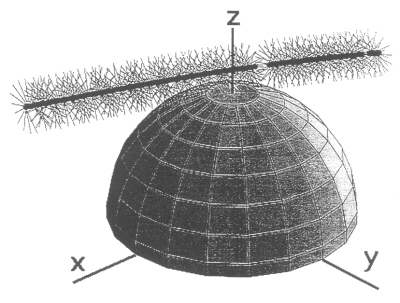 |
Figure 3.15 Trajectory of the Galileo spacecraft at the G2 encounter in GSII coordinates. The look directions of the EPD detector are shown. The spinning of the spacecraft and the stepping of the motor can be seen from the orientation of the look vectors along the trajectory. |
At this point, the pertinent coordinate systems have been defined, the important characteristics of the EPD detector have been laid out, and the direction the EPD detector is looking and the position of Galileo as a function of time can be calculated from the SPICE kernel system. The next important piece of the puzzle is establishing the model of the magnetic field that Galileo is traversing through. Chapter 4 introduces the current views in magnetic field modeling as well as some older but vital methods. At the end of Chapter 4 there will be two magnetic field models to evaluate: model M1 which is the UCLA superposition model, and model M2, derived in Chapter 4 using magnetopause and tail currents.
Next: Chapter 4 Magnetic Field Models
Return to dissertation table of contents page.
Return to main
Galileo Table of Contents Page.
Return to Fundamental
Technologies Home Page.
Updated 8/23/19, Cameron Crane
QUICK FACTS
Mission Duration: Galileo was planned to have a mission duration of around 8 years, but was kept in operation for 13 years, 11 months, and 3 days, until it was destroyed in a controlled impact with Jupiter on September 21, 2003.
Destination: Galileo's destination was Jupiter and its moons, which it orbitted for 7 years, 9 months, and 13 days.