


The Galileo Energetic Particles Detector
Galileo EPD Handbook
Chapter 1. Instrument Summary
Charged Particle Response of Magnetic Deflection System for Galileo Jupiter Orbiter (draft) (continued)
Galileo LEMMS Simulation
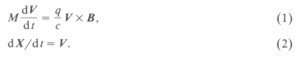
Figure 1 shows a cross section of the LEMMS assembly to be modeled in this work. When particles such as electrons or protons enter the sensor, they immediately experience a strong magnetic field in comparison with the ambient magnetic field. The field is produced by two tilted rare-earth magnets and shaped by pole pieces and a permeable yoke. The particles are deflected according to the Lorentz force, yielding the equations of motion in cgs units:
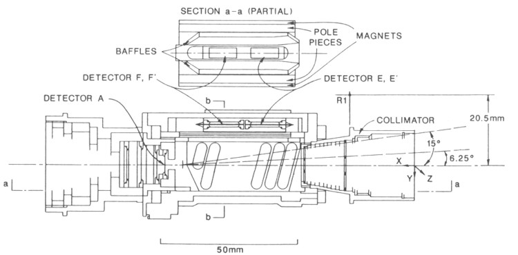 |
Figure 1. Cross section of LEMMS assembly. R1 is the reference point for the magnetic field, and it is also the origin of the coordinates used in this study. E is the lower energy electron detector, F the higher energy electron detector, and A is the proton detector. |
With a given initial position and velocity, the incoming particle can go through the sensor and enter the detectors or it may collide with the surfaces of the sensor. It may cause ion desorption from the surfaces or secondary electron emission. The particles may radiate or collide with other particles inside the sensor. However, these effects are considered marginal in comparison with the particle flux detected by electron and proton detectors and have been neglected.
The simulated LEMMS consists of two rectangular electron detectors (E and F), a circular proton detector (A), several side surfaces, and seven hexagonal incoming particle apertures, each of which has a channel, as shown in Figure 2. The aperture surface is trapezoidal and is located at one end of the sensor. Seven channels are mounted on this aperture surface. Each channel has six polygons. The two magnets are perpendicularly connected with the left and right sides of the aperture surface. The electron detector surface is placed at the smaller side of the trapezoid. Detector E is used to detect lower energy electrons and detector F higher energy electrons. The proton detector is placed directly in line with the open apertures because protons do not experience large deflection.
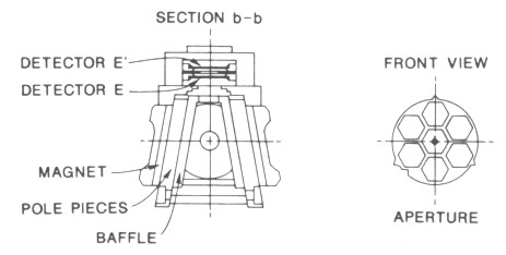 |
Figure 2. Left: Cross section of the magnetic and pole pieces. Right: aperture area display. |
We modeled the two electron detectors E and F and the proton detector A and their responses by determining the conditions of the particles which can be collected by the detectors. These conditions are the positions, angles, and energies (velocities) on incoming and outgoing particles. Then, the asymptotic behaviors of electrons and protons, such as their angular distribution, can be evaluated. The geometric factor of a detector can be determined by summing over the open solid angle at each tested detector segment.
Next: Magnetic Field Model
Return to Galileo EPD Handbook Table of Contents Page.
Return to main
Galileo Table of Contents Page.
Return to Fundamental
Technologies Home Page.
Updated 8/23/19, Cameron Crane
QUICK FACTS
Mission Duration: Galileo was planned to have a mission duration of around 8 years, but was kept in operation for 13 years, 11 months, and 3 days, until it was destroyed in a controlled impact with Jupiter on September 21, 2003.
Destination: Galileo's destination was Jupiter and its moons, which it orbitted for 7 years, 9 months, and 13 days.