Investigation of the Magnetosphere of Ganymede with Galileo's Energetic Particle Detector
Ph.D. dissertation by Shawn M. Stone, University of Kansas,
1999.
Copyright 1999 by Shawn M. Stone. Used with permission.
2.2 The Guiding Center Equation of Motion
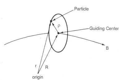
The guiding center equation of motion is the gyromotion average of the Lorentz force equation. It lends itself well to the visualization and quick calculation of the average motion of the particle. Figure 2.2 shows a charged particle gyrating about a magnetic field line where r is the position vector of the particle from some origin, R is the position vector of the gyrocenter, and ρ is the gyroradius position vector.
Figure 2.2 Schematic of a particle gyrating about a magnetic field line. The position of the guiding center is R, the position of the particle is r, and the position of the particle relative to the guiding center is ρ [Lyons and Williams, 1984].
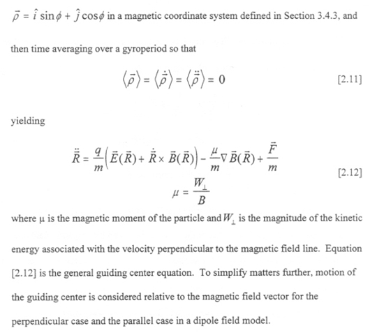
The guiding center equation of motion is obtained [Northrop, 1963; Walt, 1994] by substituting r=R+ρ into Equation [2.3]. Taylor expanding the electric and magnetic fields about the guiding center provided |R| >> |ρ|, taking
2.2.1 Motion Parallel to the Magnetic Field R||B
For the case where R||B, E=0, and F=0, Equation [2.12] simplifies to
|
|
[2.13] |
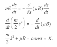
and taking R|| to be displacement along the field line R|| --> S gives
|
|
[2.14] |
If ds/dt is multiplied into Equation [2.14] and µ is taken as constant for now, then [2.14] becomes the conservation of energy equation:
|
|
[2.15] |
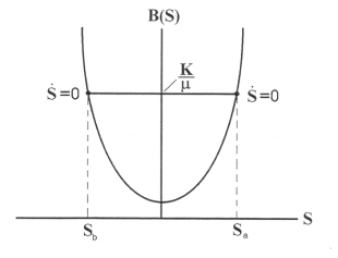
Figure 2.3 shows the physical situation that Equation [2.15] implies for a dipole geometry. As the guiding center of the particle travels up the magnetic field line it reaches point Sa where B=K/µ and ds/dt=0. A restoring force then pushes the particle back down the field line. This point is known as the mirror point of the particle. The particle travels in the opposite direction along the field line only to come to another mirror point Sb where the effect is repeated. The trajectory of the particle is trapped to bounce back and forth between mirror points Sa and Sb. This is known as a magnetic bottle or magnetic mirror geometry.
Figure 2.3 (A - left) Graphical solution to equation [2.14] in a dipole field geometry. There are two zeros for ds/dt at B=k/µ at Sa and Sb where the velocities along the field line are 0 and the particle is reflected in the other direction. (B - right) The resulting motion is a bounce motion between Sa and Sb which are called mirror points.
 |
 |
2.2.2 Motion Perpendicular to the Magnetic Field

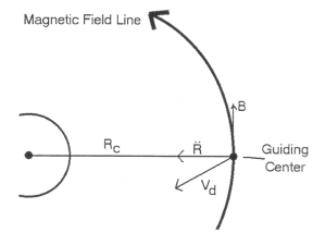
The first term in Equation [2.16] describes what is called curvature drift, shown in Figure 2.4a. If the magnetic field line is curved, then the guiding center experiences a centripetal force radially inward as the particle travels up the field line. This produces a drift perpendicular to the magnetic field line that is charge dependent; ions and electrons drift opposite of each other. The second term in Equation [2.16] is called the gradient drift, which is shown in Figure 2.4b. As the particle gyrates it experiences a non-homogenous magnetic field. Its gyroradius varies from smaller in stronger fields to larger in weaker fields. This two-step-forward one-step-back motion leads to a drift in the direction perpendicular to the magnetic field and its gradient. The direction of gradient drift is also charge dependent. Figure 2.5 shows the combined motions of charged particles in a magnetosphere with gyration, bounce, and drift.
Figure 2.4 (A - left) Curvature drift: The velocity an ion would drift (Vd) whose guiding center moves along a curved field line of radius of curvature Rc. (B - right) Gradient drift: The non-uniformity of the magnetic field allows the particle to experience regions of strong and weak field. The gyroradius of the particle is smaller in strong fields than in weaker fields.
 |
 |
Figure 2.5 Particles trapped in the magnetosphere of the Earth perform three basic motions: gyration about the field line, bounce between mirror points, and azimuthally drift about the planet. The drift due to curvature and gradient drifts are charge dependent and cause the proton and electron drift to be opposed [Walt, 1994].

Next: 2.3 Adiabatic Invariants
Return to dissertation table of contents page.
Return to main
Galileo Table of Contents Page.
Return to Fundamental
Technologies Home Page.
Updated 8/23/19, Cameron Crane
QUICK FACTS
Mission Duration: Galileo was planned to have a mission duration of around 8 years, but was kept in operation for 13 years, 11 months, and 3 days, until it was destroyed in a controlled impact with Jupiter on September 21, 2003.
Destination: Galileo's destination was Jupiter and its moons, which it orbitted for 7 years, 9 months, and 13 days.


