Investigation of the Magnetosphere of Ganymede with Galileo's Energetic Particle Detector
Ph.D. dissertation by Shawn M. Stone, University of Kansas,
1999.
Copyright 1999 by Shawn M. Stone. Used with permission.
6.3.1 Feature G2-18:56:31
The channel A4 ion results for one shot mode are shown in Figures 6.56 (model M1) and 6.57 (model M2) for feature G2-18:56:31. As can be seen in both figures, pitch and phase angles are matched by both models very well. The shape and depth of the loss cone is also matched well by both models. The electrons show a more interesting story. The lower energy electrons (channels E0 to E3) are matched in much the same way as the ions, as shown in Figures 6.58 (model M1) and 6.59 (model M2) for channel E3. The only difference seems to be that the width of the actual electron loss cone is a bit wider than the simulated results. However, a look at the higher energy electrons (channels F1 to F3) shows an anti-moon loss cone near a pitch of 180°, where the lower energy electrons do not. Figures 6.60 and 6.61 show the results for channel F2 in one shot mode.
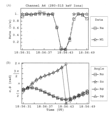 |
Figure 6.56 (A) Simulated M1 and real (Re) rate profile for feature G2-18:56:31 of Channel A4 normalized to 90º pitch. (B) The pitch and phase angles are computed from the look direction of the EPD detector and the appropriate magnetic field vector R for real and S for simulated. |
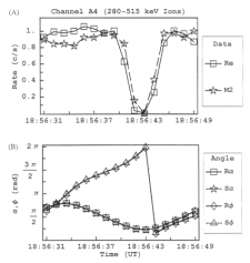 |
Figure 6.57 (A) Simulated M2 and real (Re) rate profile for feature G2-18:56:31 of Channel A4 normalized to 90º pitch. (B) The pitch and phase angles are computed from the look direction of the EPD detector and the appropriate magnetic field vector R for real and S for simulated. |
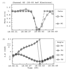 |
Figure 6.58 (A) Simulated M1 and real (Re) rate profile for feature G2-18:56:31 of Channel E3 normalized to 90º pitch. (B) The pitch and phase angles are computed from the look direction of the EPD detector and the appropriate magnetic field vector R for real and S for simulated. |
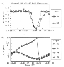 |
Figure 6.59 (A) Simulated M2 and real (Re) rate profile for feature G2-18:56:31 of Channel E3 normalized to 90º pitch. (B) The pitch and phase angles are computed from the look direction of the EPD detector and the appropriate magnetic field vector R for real and S for simulated. |
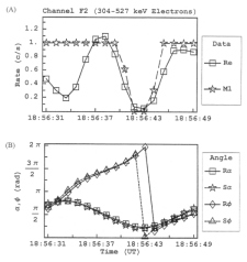 |
Figure 6.60 (A) Simulated M1 and real (Re) rate profile for feature G2-18:56:31 of Channel F2 normalized to 90º pitch. (B) The pitch and phase angles are computed from the look direction of the EPD detector and the appropriate magnetic field vector R for real and S for simulated. |
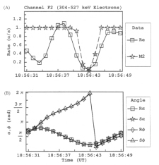 |
Figure 6.61 (A) Simulated M2 and real (Re) rate profile for feature G2-18:56:31 of Channel F2 normalized to 90º pitch. (B) The pitch and phase angles are computed from the look direction of the EPD detector and the appropriate magnetic field vector R for real and S for simulated. |
An investigation in extended bounce mode with the addition of a scattering mechanism was then implemented, since the difference in the bounce times of the electrons could explain why the lower energy electrons do not seem to interact with Ganymede a second time, but the higher energy ones do. Also, for the anti-moon loss cone for channel F2, there is the appearance of a filling in of the loss cone which may be due to scattering. Figures 6.62 and 6.63 show these results for four traces with varying scattering coefficient for model M1. As can be seen in these figures, an anti-moon loss cone is attained, and with the addition of scattering both the loss cones at pitch angle near 0° and 180° can be recovered. Figures 6.64 and 6.65 show similar results for model M2 with varying scattering coefficient.
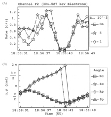 |
Figure 6.62 (A) Simulated M1 and real (Re) rate profile for feature G2-18:56:31 of Channel F2 normalized to 90º pitch. The simulated runs are done in extended bounce mode with scattering included. Scattering coefficients are 5 and 1. B) The pitch and phase angles are computed from the look direction of the EPD detector and the appropriate magnetic field vector R for real and S for simulated. |
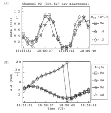 |
Figure 6.63 (A) Simulated M1 and real (Re) rate profile for feature G2-18:56:31 of Channel F2 normalized to 90º pitch. The simulated runs are done in extended bounce mode with scattering included. Scattering coefficients are .6 and .2. (B) The pitch and phase angles are computed from the look direction of the EPD detector and the appropriate magnetic field vector R for real and S for simulated. |
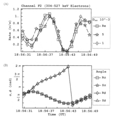 |
Figure 6.64 (A) Simulated M2 and real (Re) rate profile for feature G2-18:56:31 of Channel F2 normalized to 90º pitch. The simulated runs are done in extended bounce mode with scattering included. (B) The pitch and phase angles are computed from the look direction of the EPD detector and the appropriate magnetic field vector R for real and S for simulated. |
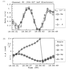 |
Figure 6.65 (A) Simulated M2 and real (Re) rate profile for feature G2-18:56:31 of Channel F2 normalized to 90º pitch. The simulated runs are done in extended bounce mode with scattering included. (B) The pitch and phase angles are computed from the look direction of the EPD detector and the appropriate magnetic field vector R for real and S for simulated. |
Return to dissertation table of contents page.
Return to main
Galileo Table of Contents Page.
Return to Fundamental
Technologies Home Page.
Updated 8/23/19, Cameron Crane
QUICK FACTS
Mission Duration: Galileo was planned to have a mission duration of around 8 years, but was kept in operation for 13 years, 11 months, and 3 days, until it was destroyed in a controlled impact with Jupiter on September 21, 2003.
Destination: Galileo's destination was Jupiter and its moons, which it orbitted for 7 years, 9 months, and 13 days.


