Investigation of the Magnetosphere of Ganymede with Galileo's Energetic Particle Detector
Ph.D. dissertation by Shawn M. Stone, University of Kansas,
1999.
Copyright 1999 by Shawn M. Stone. Used with permission.
3.2 Low Energy Magnetospheric Measurement System (LEMMS)
The LEMMS detector head is a double-ended telescope designed to measure ions from 22 keV to 55 MeV and electrons from 15 keV to 11 MeV. It takes data at one of three rates: 1/3, 2/3, and 4/3 s, which results in angular resolutions of 6°, 12°, and 24° sectors respectively. The LEMMS detector houses 6 solid state detectors.
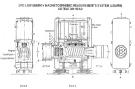
Detectors E1, E2, F1, and F2 register counts for the electrons. Detectors A and B register counts for the ions. Particles entering through the 15° full angle collimator at the 0° end are separated into ions and electrons by an inhomogeneous magnetic field. The electrons are deflected upwards toward the E and F detectors while the ions are virtually undeflected and encounter the A and B detectors. Detectors C and D at the 180° end along with absorbers in combination provide measurements of ions >=16 MeV and electrons >=2 MeV [Williams et al., 1992].
3.2.1 Low-Energy Ion Telescope: Detectors A and B
Detectors A and B are the primary set of detectors for measuring low energy ions (Z>=1) in the Jovian magnetosphere. The ions that enter the collimator pass through a series of eleven baffle plates that define seven hexagonal entrance aperture channels converging toward detector A. This geometry, shown in Figure 3.4, provides a relatively wide aperture with the narrowly-defined total acceptance angle necessary for the focused deflection of electrons in the shaped magnetic field beyond the aperture plates. Electrons <= 1 MeV are deflected away from detector A and focused onto detectors E and F for analysis. Ions pass through the field region with relatively little deflection and impact on detector A. Detector A is a 25 square mm in area with 102 μm thick surface barrier. Detector B is 35 square mm in area and 984 µm thick. Ions impacting A are measured in 8 differential rate channels covering the energy range from 22 keV to 3.2 MeV. Table 3.2 shows how the ion channels are partitioned. Background contamination at Jupiter is minimized by coincidence/anti-coincidence conditions between detectors, and by surrounding platinum-iridium shielding [Williams et al., 1992].
 |
Figure 3.4 Cross-section of the LEMMS detector. Both ion and electron detectors are shown. Particles enter the 0° end of the telescope and electrons are magnetically deflected up towards the E and F detectors. Ions remain virtually undeflected and impact detectors A and B [Williams et al., 1992]. |
Table 3.2 LEMMS A channels and passband energies
| Channel Name | Energy Range (keV) |
| A0 | 22-42 |
| A1 | 42-65 |
| A2 | 65-120 |
| A3 | 120-280 |
| A4 | 280-515 |
| A5 | 515-825 |
| A6 | 825-1680 |
| A7 | 1680-3200 |
3.2.2. Low-Energy Electrons: Detectors E1, E2; F1, F2
Figure 3.4 shows the collimator and magnetic deflection region of the low energy end of the LEMMS telescope. Permanent magnets produce an inhomogeneous magnetic field between inclined pole pieces with a maximum center line strength of 50 G. Entering electrons are focused onto E1 (>=15 to 200 keV) and F1 (100 to > 1 MeV), which provide low energy electron measurements for the EPD experiment. Both detectors are rectangular, 45 square mm surface barrier silicon detectors. E1 is 303 µm thick, and F1 is 1097 µm thick. Both detectors are backed by 300 µm thick (E2, F2) detectors of equal area operated in anti-coincidence to actively reduce any background particles penetrating the surrounding shielding of >=6 g cm-2 of platinum-iridium alloy. The outputs of detectors E1 and F1 are registered in eight differential accumulator-based fast rate channels and are partitioned according to Table 3.3. The F0 channel is the sum of ~100 to 200 keV events seen in both detectors E1 and F1 [Williams et al., 1992].
Table 3.3 LEMMS E and F channels and passband energies
| Channel Name | Energy Range (keV) |
| E0 | 15-29 |
| E1 | 29-42 |
| E2 | 42-55 |
| E3 | 55-93 |
| F0 | 93-188 |
| F1 | 174-304 |
| F2 | 304-527 |
| F3 | 527-304 |
Next: 3.3 Count Rate and Differential Particle Flux
Return to dissertation table of contents page.
Return to main
Galileo Table of Contents Page.
Return to Fundamental
Technologies Home Page.
Updated 8/23/19, Cameron Crane
QUICK FACTS
Mission Duration: Galileo was planned to have a mission duration of around 8 years, but was kept in operation for 13 years, 11 months, and 3 days, until it was destroyed in a controlled impact with Jupiter on September 21, 2003.
Destination: Galileo's destination was Jupiter and its moons, which it orbitted for 7 years, 9 months, and 13 days.


